|
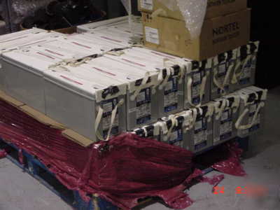
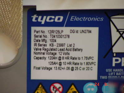
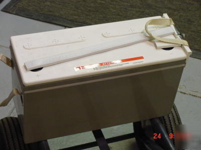
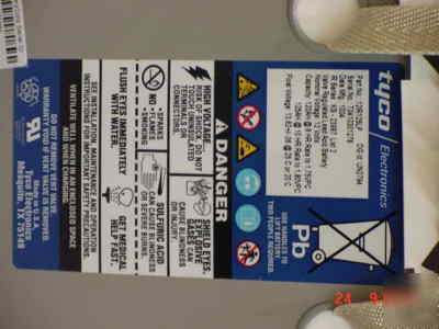
Visit our store for hundreds of other bargains. Taken out of service last month all batteries fully charged. Specs: On battery Label P/N 12IR125LP Valve Regulated Lead Acid Battery Capacity 120AH @ 8HR Rate to 1.75 VPC 125 AH @ 10 HR Rate to 1.80 VPC Flot Voltage 13.62 +/- .06 @ 25c or 20c. Maximum length for 12IR125 and 12IR150 is from dimple to dimple on can. Maximum length for 12IR125LP and 12IR150LP is from dimple on can to terminal protective shield. Maximum width for 12IR125, 12IR125LP, 12IR150, and 12IR150LP is from dimple to dimple on the can. Batteries shall be charged by a constant voltage method. A voltage of 13.50 0.06 volts per 12 V battery for constant voltage is recommended for float-standby applications at 77 F (25 C). For systems without a temperature compensation device, the float voltage should be reduced by 18mV/ C/battery for temperatures above 25 C (77 F). This adjustment is automatically performed in systems with either a step or a slope compensation device. Caution: Failure to reduce float voltage in systems without temperature compensation may result in premature failure or thermal run-away. Operating 12IR125/LP or 12IR150/LP batteries for any length of time outside the recommended voltages and/or temperatures will result in reduced performance and premature failure and may reduce It is extremely important to maintain the battery at the proper float voltage. The recommended float voltage per battery is 13.50 volts 0.06 volts at a battery tem- The 12IR125/LP & 12IR150/LP batteries are provided with inter-battery bus bars to connect batteries in series to create battery strings. One bus bar is provided with the accessory kit and comes complete with hardware to cre- ate various size strings of batteries as specified for the application (e.g., 24V or 48 V battery strings). When planning or installing the 12IR125/LP or 12IR150/LP batttery, refer to Figure 4 or 5 to determine battery spacing. These two figures show the maximum and minimum spacing of the batteries when they are positioned end to end either short face to short face or NOTE: Do not refer to these figures for help in connecting the batteries in strings. These figures are not intended to depict wiring options. Battery Installation Procedure 1. Before proceeding with the installation of the battery, review or determine the arrangement of the batteries 2. The battery terminals are precoated with NO-OX-ID A compound. If terminals appear dirty, clean surface areas of the exposed terminals with a non-abrasive cloth and (provided with accessory kit). container, clean the case with a cloth dampened with water before installing it in the battery stand. Caution: Use only water to clean batteries. 4. Gently slide batteries into position as determined in Step 1. The battery should be oriented so that the nega- tive ( ) post of one battery is adjacent to the positive (+) post (post of opposite polarity) of next or adjacent battery. Caution: Do not lift the battery (ies) alone or with one handle. Two persons are recommended to lift the battery. Hoist battery on pallets or use lifting 5. Coat inter-battery bus bars, provided with battery kit, before assembling them to batteries. 6. Using 1/4-20 hardware and inter-battery bus bar pro- vided, connect batteries into strings as determined in the first Installation Procedure, (See Figure 2). Torque 7. Using cabling provided with the plant, connect the battery string to the plant bus as determined in Step 1. Terminate these cable leads with the appropriate wire lugs. 8. Dress the cable leads from the batteries to the plant bus work and torque battery connections to 60 in-lbs. See specifications provided with the plant for plant bus work (Tyco batteries lot sale 30 each. p/n 12IR125LP was posted and is owned by: Johanna Valentine) |
johanna.valentine@chicagopartsnetwork.com (Johanna Valentine) for more information.