|
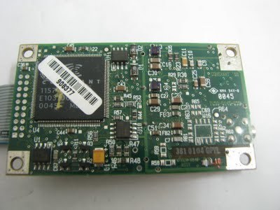
I based mine on a similar circuit. The 7404 can be used to buffer the 10KHz and 1 Hz output. The simple interface has worked on all serial ports I have tried. All that is needed is 5 volts, the simple computer interface (to set it up and check it is working), and an antenna. It will work with a home made dipole. The 10KHz output could be divided down, for example a 74390 would divide by 2,2,5,5 giving 100Hz minimum frequency. This can be applied to the antenna socket of the RX via an attenuator (just a variable potentiometer). SpecLab ( http://www.qsl.net/dl4yhf/spectra1.html ) would then show a marker every 100Hz. Harmonics of the basic 10KHz are useful on HF. For absolute accuracy the 10KHz should be used to lock an OXCO but I suspect the raw signal may well be adequate except for the most exacting requirements. It is possible to power this unit from a USB port (about 200mA). One way could be to use a USB/Serial adaptor, if it is the type with the control electronics at the far end of the cable the power could be taken by breaking the cable. UPDATE:- ON SOME SYSTEMS USB POWER WILL NOT WORK, I HAVE SEEN THE USB VOLTAGE AT LESS THAN 5.0, SOMETIMES TOO LOW TO SATISFACTORILY POWER THE GPS. For the experimenter, USB mobile telephone connectors usually contain a USB/Serial converter. These are available cheaply, or unwanted ones may be free. It MAY be possible to open one up and adapt it. I managed this with an Ericsson DCU-11 adapter. The Cygnal CP2101 inside runs on 3V0 so needs a simple interface to the 5V0 of the Rockwell. As with many components, a "Google" will often find details of the ICs. Incidently the Khune crystal heater CAN transform a receiver, my old ICR70 is stable within +/- 1 Hz for days with two of these fitted. =aboved from http://homepages.wightcable.net/~g4zfq/chirp.htm____= Jupiter TU30-D140 GPS receiver module 1pps 10khz larger imageRockwell Jupiter TU30-D140 GPS receiver module 1pps 10khz Rockwell Jupiter TU30-D140 GPS receiver module 1pps 10khz Rockwell jupiter Tu30 GPS 1pps 10khz The Rockwell Jupiter TU30-D140 / TU30-D145 - 039 is a OEM only for CR Designed-GPS receiver module that is designed to be implemented as part of a larger design, like a vehicle tracking system, navigational system, time/clock reference etc. (by lungo) This is a 12 parallel-channel all-in-view receiver. The module is 4 by 7 cm, and has a 20 pins connector for the various signals and power supply's and a MCX connector to for the GPS antenna. (by lungo) This 20-pin header has all the power supply, input and output signals exept the GPS antennasignal. The header has a 2.0 mm pitch, which is not very common. It is possible to create an adapter using a 2.5"-to-3.5" convertor PCB meant to connect laptop harddiscs to normal pc's. These can be bought in PC shops for around 10 euro. This adapter needs some work before you can use it. Some points are connected together on ground, and some points are not connected at all. With a sharp knife and some short pieces of wire you can cut away the unwanted ground connections and make a 1-to-1 adapter. 2mm pitch connectors are also used for internal wiring in mouse units and floppy disc drives. Another possibility is to remove the contacts from a ic-socket, the type with tooled bus-contacts (Augat), and use these to connect wires. Or you can directly solder wires to the pins or make a special PCB. 20p connector signal description pin 1 (square solder island) (by lungo) Power supply for the active antenna. This voltage is put on the center conductor of the antenna connector. Do NOT USE it with a passive antenna!! Maximum of 12V @ 100mA. Most of the active antenna's work at 5V or even 3.3V for the newest types and consume between 15 and 50 mA. (by lungo) pin 2Supply for the receiver itself. Should be 5V +/- 0,25V. The receiver consumes about 200mA. When in MR-active mode (see below) around 100mA. The absolute minimum for the receiver to operate is 4.5V. (by lungo) pin 3Battery backup power input. This 3 to 5V input feeds the static ram and real-time clock chips of the module when there is no power supplied on pin 2. Current consumption is then (and only then) between 40uA(3V) to 80uA(5V). This voltage is needed to keep the real-time clock running and static ram contents valid. This is again needed to keep te re-aquisition time as short as possible. You can use a small NICD or NIMH cell with a charging circuit, or a goldcap. A lithium cell can be used, but only if the receiver would be in operation most of the time, since the current consumption would drain a Li cell in a few weeks. (by lungo) pin 4Slot hole - no pin - Not in use (by lungo) pin 5Master Reset. The receiver is reset if this line is pulled to ground. As long as the line is 'low' the receiver is in a low-power mode. However, low-power mode in this case still means a 100mA current consumption. (by lungo) pin 6, 9 and 14reserved - do not connect anything or ask me for more information (by lungo) pin 7 & 8These are digital inputs that define the startup mode of the receiver. These must either be connected to ground level, of pulled-up with a 10k resistor to +5V (by lungo) When this line is low (ground) the receiver will always start in NMEA-0183 mode: ascii messages in 4800bd, no parity, 8 databits and 1 stopbit. If this line is pulled high the start mode is determined by the state of pin 8. (by lungo) If this line is pulled to ground the receiver will always start with the factory default values from the preprogrammed ROM memory. When this line is high the initial values are taken from static ram (if a battery was connected to pin 2) or from eeprom. These initial values include the last known position and date/time, satellite orbital data, communication parameters etc. (by lungo) For most of the applications you will want pin 7 to be low and pin 8 to be high. The receiver will than always start in NMEA0183 mode and uses the data in sram / eeprom for the initial calculations. See for more details the datasheet jupiter-gps-board.pdf @ (by lungo) pin 10,13,16,17 and 18Ground. These pins should all be connected to ground. (by lungo) pin 11 and 12Serial output (11) and input (12). This is the main serial port over which the application (pc, laptop, aprs etc) communicates. These lines work on TTL levels. To be able to talk with a PC you need a ttl<>rs232 converter like a MAX232 or a LT1281. Although the rs232 levels officially are +3..+12V for a "0" or "on" and -3..-12V for a "1" or "off", most of the pc's and laptops also work fine with 5V and 0V. If you want to try this, all you need is a 74HCT04 cmos inverter and some passive components. (by lungo) pin 15Serial input, also on TTL level. This port is meant for RTCM104 differential gps correction messages. * No special configuration is neccesary - if valid dgps data is supplied the receiver will adjust its calculations accordingly.(by lungo) pin 19 1 PPS (puls per second) signal. This is a TTL signal with a frequency of exactly 1 Hz. The pulse length is exactly 25.6 ms and the rising edge is within 1us from the UTC second transition. There is software available that synchronizes the time in your PC and that expects a 1pps signal on the DCD line, so if you make an interface yourself you could use this. (by lungo) pin 2010 kHz TTL signal. This signal is also synchronous with pin 19 and has a long-term accurate to 1uHz (microhertz) or better, if the receiver has a "fix" on the GPS satellites. (by lungo) manual. and software available (Rockwell jupiter TU30 gps receiver module 1PPS 10KHZ was posted and is owned by: Wilda Long) |
wilda-long@chicagopartsnetwork.com (Wilda Long) for more information.